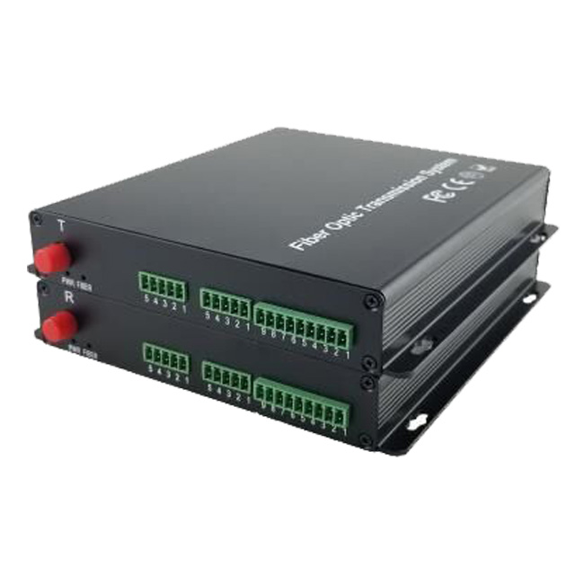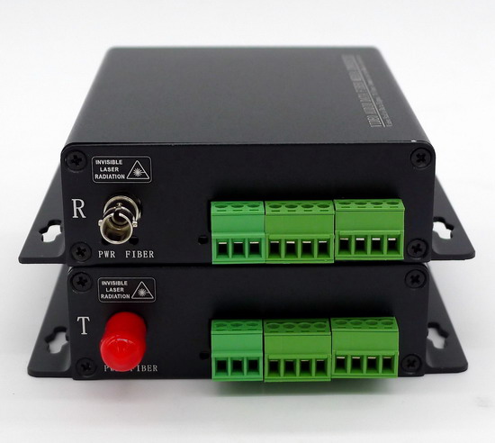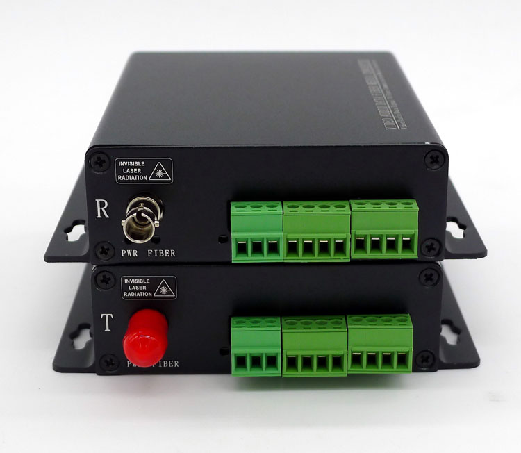

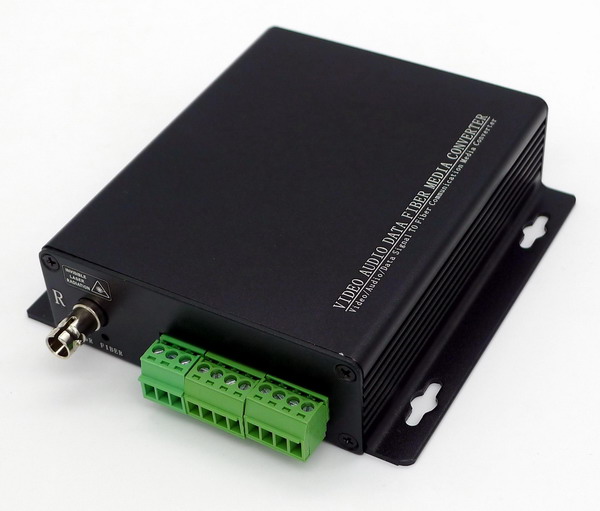
Description
2 ch Contact Closure To Fiber Optic support 2 ch contact closure over one multi-mode or single-mode optical fiber. These fiber optic transmitterand fiber optic receiver are typically used in applications with Access Control System, Alarm Event Triggering, Building Automation and Environmental Control Systems, Fire & Alarm Systems, PIR signal Transmission, Traffic Signal Control Equipment, etc, and are available for stand-alone or rack-mount installations. FC, ST or SC optical connectors is optional.
Plug and Play design ensures adjustment-free installation and operation, and optical adjustments are never required. LED indicators are provided to instantly monitor the system operating status.
Features
• Support Point-to-Point or Daisy-Chain connection
• Dry Contact Closure or TTL data over one fiber
• Multimode Fiber Support for Distances up to 2 km
• Single-Mode Fiber Support for Distances up to 100 km
• LED Status Provide Rapid Indication of Operating Parameters
• No EMI or RFI and no ground loops
• Stand alone or rack-mount
• Produce according to customer's specifications,providing OEM
Opitcal:
|
Wavelength |
1310nm&1470nm~1610nm |
|
Output Power |
-14~ -8dBm / -5~0dBm |
|
Optic fiber |
50/125u multimode,62.5/125u multimode,9/125u single mode |
|
Rx sensitivity |
-30dBm |
|
Optical connector |
FC、ST、SC (optional) |
|
Distance |
0~2KM (MM) / 0~100KM (SM) |
Contact Closure:
|
Connector |
Standard terminal lead |
|
Signal input |
alarm, Binary input, support TTL、RS-232/422/485 or passive dry Contact Closure |
|
Signal output |
Arbitrary alarm, Binary output, support TTL、RS-232/422/485 or relay output |
|
Electrical & Mechanical |
|
|
Input Power Requirements: |
DC 5V@2A |
|
Power Adapter: |
AC 90V~240V |
|
Power Consumption: |
< 3W |
|
Stand-Alone Dimensions: |
104mm × 104mm × 28mm |
|
Shipping Weight: |
(include Transmitter & Receiver ) 0.75kg |
|
Environmental |
|
|
Operating Temperature: |
-20°C ~ +75°C |
|
Storage Temperature: |
-40°C ~ +85°C |
|
Relative Humidity: |
0% ~ 95% (non-condensing) |
|
MTBF: |
>100,000 hours |
System connection diagram